Driver Atomic Pc Pad Converter Cc
Intel® Edison
| Intel® Edison Front | Intel® Edison Back |
On this page... (hide)
This package supports the following driver models:USB Vibration Gamepad. Windows 2000 SP 1; Windows 2003 64-bit; Windows 2003 AMD 64-bit; Windows XP 64-bit SP 2; Windows NT 4 SP 3; Windows 2000 SP 2; Windows Server 2003 x64 R2; Windows 2000; Windows 2003 64-bit SP 1; Windows Vista AMD 64-bit.Missing.
- Overview
Overview
Intel® Edison Module
The Intel® Edison module is a SoC (System on Chip) that includes an Intel® Atom™ 500MHz dual-core, dual-threaded CPU and an Intel® Quark™ 100MHz microcontroller.
Key features:
- Integrated Wi-Fi, Bluetooth 4.0 LE;
- Support for Yocto Linux, Python, Node.js and Wolfram
Intel® Edison with Kit for Arduino
| Intel® Edison Kit for Arduino Front | Intel® Edison Kit for Arduino Back |
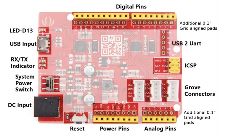
Intel® Edison Kit for Arduino provides the Arduino 1.0 pinout and standard connectors such as a micro USB connected to a UART, a USB OTG port that can be switched between a second micro USB device connector, a standard size USB host Type-A connector, a uSD card holder, and a DC power jack.
Like an Arduino Uno, the Intel® Edison Kit for Arduino makes possible to have provides 20 digital input/output pins, of which 6 can be used as analog inputs. The Intel® Edison has 4 PWM outputs which can be configured via jumpers to any of the 6 pins supporting PWM on the Arduino Uno (pins 3, 5, 6, 9, 10, or 11).
The Intel® Edison Kit for Arduino is designed to be hardware and software pin-compatible with Arduino shields designed for the Arduino Uno R3. Digital pins 0 to 13 (and the adjacent AREF and GND pins), Analog inputs 0 to 5, the power header, ICSP header, and the UART port pins (0 and 1), are all in the same locations as on the Arduino Uno R3.
The digital IOs and analog pins can be configured to operate at either 5V or 3.3V. The outputs can source or sink 24 mA at 3.3V and 32 mA at 5V.

Intel® Edison with Breakout Board
| Intel® Edison Breakout Board Front | Intel® Edison Breakout Board Back |
The Intel® Edison Breakout Board is designed to expose the native 1.8V I/O of the Intel® Edison module. The boardconsists of power supply, battery recharger, USB OTG power switch, UART to USB bridge, USB OTG port, and I/Oheader.
Summary
| SoC | Dual-core, dual-threaded Intel® Atom™ CPU and a 32-bit Intel® Quark™ microcontroller |
| Operating Voltage | 1.8V (Breakouk Board) |
| 3.3V / 5V (Kit for Arduino | |
| Input Voltage | 7-15V (Both Breakout Board and Kit for Arduino |
| Digital I/O Pins | 20 (of which 6 provide analog input and 4 provide PWM output) (Kit for Arduino) |
| Flash Storage | 4 GB eMMC |
| RAM | 1 GB LPDDR3 POP |
| Clock Speed | 500 MHz (Intel® Atom™ CPU) |
| 100 MHz (Quark™ microcontroller) | |
| Length | 35.5mm (Edison) |
| 61mm (Breakout Board) | |
| 127mm (Kit for Arduino) | |
| Width | 25mm (Edison) |
| 29mm (Breakout Board) | |
| 72mm (Kit for Arduino) | |
| Height | 4mm (Edison) |
| 12mm (Breakout Board) | |
| 12mm (Kit for Arduino) |
Jumpers
Intel® Edison Breakout Board
- J2 is the battery connector. If you want to power the breakout board with a rechargeable lithium-ion battery,
attach it to J2. (Refer to the figure for battery polarity.) When you attach a rechargeable lithium-ion battery,the breakout board will recharge the battery whenever power is applied via J21 or J22, or via J3 (when theboard is attached to a USB host). Note that If you decide to use a battery pack on J2, we recommend a battery with a built-in thermistor. This thermistor should attach to the charger on the breakout board. If you opt for the built-in thermistor,remove the jumper on J1 and connect the thermistor to the pin labeled THERM in the figure. If youchoose not to use a battery with built-in thermistor, leave the jumper in place.)
- J3 is a micro USB FTDI serial-to-USB converter. The Linux console will output serial stream to this USB
connector.
- J16 is a fully USB compatible, micro AB, OTG (power “on the go”) port. If you plug a micro A cable into this
port, the Intel® Edison module will connect to a PC as the host; if you plug a micro B cable into this port, theIntel® Edison module will connect to the PC as a device.
- For jumpers J17 through J20, the first pin on the left (the square one) is pin 1.
- J21 is the main power input. Apply 7 to 15 VDC with the polarity shown.
- J22 (on the bottom side of the board; see Figure 3) is for a power jack (not installed). You can purchase a
2.5 mm barrel jack and solder it to the bottom side of the board as shown in Figure 3. The input voltage to J22is also 7 to 15 VDC.
Intel® Edison Kit for Arduino
- J1 is the main power input. Apply 7 to 15 VDC with the positive center.
- J2 is the battery connector. If you want to power the breakout board with a rechargeable lithium-ion battery,
attach it to J2. (Refer to the silk for battery polarity.) When you attach a rechargeable lithium-ion battery,the Kit for Arduino will recharge the battery whenever power is applied via J3 or J16, or via J1 (when theboard is attached to a USB host).
- J11 & J12. There are four available GPIO that can be configured as PWM outputs This pin header arrangement allows the four PWM sources to be routed to any four of the six Arduino header pins. Figure 3 shows the PWM swizzler. Moving the PWM jumpers from the default configuration makes an I/O pin unavailable for use.
Driver Atomic Pc Pad Converter Cc 2
- J16 is a fully USB compatible, micro AB, OTG (power “on the go”) port. If you plug a micro A cable into this
port, the Intel® Edison module will connect to a PC as the host; if you plug a micro B cable into this port, theIntel® Edison module will connect to the PC as a device.
Power
The Intel® Edison is a low-power device. In general, it does not draw more than 200 mA with 600 mA short durationspikes during Wi-Fi transmit. Therefore, an Intel® Edison device may run on USB power (when configured as adevice), or an external power adapter from 7 to 15 V.
Driver Atomic Pc Pad Converter Cc To Download
Power from the external power adapter goes to a DC-DC converter and down-converted to 5 V. This power goes to a battery recharger IC, which limits the output voltage to 4.4 V. This voltage is in the safe range for the Edison module VSYS. The VSYS power range is 3.15 to 4.5 V. This allows the Intel® Edison device to run off a standard lithium-ion battery.
Intel® Edison Breakout BoardThe on-boardcharger IC is configured to limit the current to 1 A. The charger is programmed to charge at 190 mA. This charger is designed to charge standard lithium-ion batteries with 4.2 V maximum charging voltage. You are responsible for choosing a suitable battery and following all safety precautions, to prevent overcharging or charging when the battery temperature is too high.
The drawback to this design is that the linear supply power drop places a limit on the total power through theIntel® Edison board and the 3.3 and 1.8 V supplies. The power loss through the charger will be (4.4 to 5 V) times current.In this case, you should attempt to limit average current through the Intel® Edison board and its power rails toapproximately 0.75 A.
The recharger IC on the Intel® Edison breakout board has input current limit and overtemperature shutdown.Assure the end design does not trip these protection mechanisms.Some considerations of the power distribution in the Intel® Edison breakout board:
- USB host mode always requires use of an external power adapter.
- You are responsible for choosing a suitable battery and following all safety precautions, to prevent
overcharging or charging when the battery temperature is too high. The battery should be at least300 mAH capacity, due to the 100 mA charging current. Intel recommends battery packs with internalprotection circuits
Intel® Edison Kit for Arduino
The onboard charger IC is configured to detect the input power source and to limit the input power to either500 mA (if connected to USB micro B port) or up to 1 A if connected to the DC power jack. he charger isprogrammed to charge at 100 mA. This charger is designed to charge standard lithium ion batteries with 4.2 Vmaximum charging voltage. End-users are responsible for choosing a suitable battery and following all safetyprecautions, to assure overcharging or charging when the battery temperature is too high is avoided.For low power applications (those shields running off 3.3 V) a lithium ion battery (3.0 to 4.3 Vmax) can be attachedto J2, which will power the Intel® Edison kit for Arduino and provide 100 mA of 3.3 V to the shield.Some considerations of the power distribution in the Intel® Edison kit for Arduino:
- Due to the diode ORing of the 5 V DC/DC and the VBUS input, means the 5 V power to the shield header will
be nominally below 5 V. In the case of VBUS the voltage may be as low as 4.4 V (4.75 V VBUS min – 0.3 Vdiode drop. In the case of external power adapter 4.7 V.
- USB host mode always requires use of an external power adapter.
The power pins are as follows:
- VIN: The input voltage to the Intel board. You can access the voltage supplied via the power jack through this pin.
- 5V: This pin outputs a regulated 5V from the regulator on the board.
- 3.3V: A 3.3 volt supply generated by the on-board regulator. This regulator also provides the power supply to the Quark microcontroller.
- GND: Ground pins.
- IOREF: This pin on the Arduino board provides the voltage reference with which the microcontroller operates. This can be 3.3V or 5V based on the IOREF jumper position.
Buttons
Intel® Edison Breakout Board
The power button (SW1) is configured by software. Pressing and holding the power buttonwill produce different results depending on the current state of the Intel® Edison compute module and theduration of the hold:
- When the Intel® Edison device is completely powered down, pressing and holding the power button for
3 seconds will power up the device and boot up the Intel® Edison compute module.
- When the Intel® Edison device is running, pressing and holding the power button for more than
2 seconds but less than 7 seconds will put the Intel® Edison device into AP (access point) mode. Thisaction enables the “one-time setup” (same as configure_edison --enableOneTimeSetup).
- When the Intel® Edison device is running, pressing and holding the power button for 10 seconds or
more will cause the Intel® Edison compute module to power down. This is similar to a hard shutdown,which cuts the power supply to the compute module.
Intel® Edison kit for Arduino
- System reset. Pressing the system reset button (SW1UI5) will reset the Intel® Edison compute module, and
reset the I/O expanders, setting all the shield pins to high impedance state with no pullups.
- Shield reset. Pressing the shield reset button (SW1UI1) will pull the shield signal reset to the active low
state. It does not affect the state of the Intel® Edison compute module or its I/O.
- Power button. The power button (SW1UI2) is configured by software. Pressing and holding the power
button will produce different results depending on the current state of the Intel® Edison compute moduleand the duration of the hold:− When the Intel® Edison device is completely powered down, pressing and holding the power button for3 seconds will power up the device and boot up the Intel® Edison compute module.− When the Intel® Edison device is running, pressing and holding the power button for more than2 seconds but less than 7 seconds will put the Intel® Edison device into AP (access point) mode. Thisaction enables the “one-time setup” (same as configure_edison --enableOneTimeSetup).− When the Intel® Edison device is running, pressing and holding the power button for 10 seconds ormore will cause the Intel® Edison compute module to power down. This is similar to a hard shutdown,which cuts the power supply to the compute module.
Input and Output
Intel® Edison Breakout Board
Please refer to the hardware guide for a complete overview of the board functionalities.
Intel® Edison kit for Arduino
- Serial: 0 (RX) and 1 (TX). CTS and RTS is also available. Used to receive (RX) and transmit (TX) TTL serial data.
- Digital I/O: Digital pins 0 through 13 and Analog pins A0 through A5 can be used as a digital input or output, using pinMode(), digitalWrite(), and digitalRead() functions. They can operate at 3.3 or 5 volts.
Each pin can provide (source) or receive (sink) a current of 32mA @ 5v, or a current of 24mA@3.3V
- PWM: 4 PWM channels are available, which can be configured via jumpers to any of digital pins 3,5,6,9,10, or 11
- SPI: 10 (SS), 11 (MOSI), 12 (MISO), 13 (SCK), as well as the ICSP header
- LED: 13. There is a built-in LED connected to digital pin 13. When the pin is HIGH value, the LED is on, when the pin is LOW, it's off.
- Analog Inputs: pins A0 through A5
- SDA and SCL: Supports TWI or I2C communication
Communication

Intel® Edison Breakout Board
A complete overview about how to communicate with this board is given in this Intel Tutorial.
Intel® Edison kit for Arduino
All the communication methods listed above are valid. However the Intel® Edison Kit for Arduino has a number of facilities for communicating with a computer, another Edison, Arduino or other microcontrollers, and different devices like phones, tablets, cameras and so on.
It provides 2 UART Controllers : UART 1 to Arduino digital pins 0 and 1; UART 2 to a micro USB device connector; and a USB OTG port that can be switched between a second micro USB device connector or standard size USB host Type-A connector
The on-board microSD card reader is connected via an integrated SD controller and does not require the use of the SPI interface like other Arduino boards.
Programming
The Intel Edison can be programmed with this special version of the Arduino software.It's possible to make requests of the Linux kernel with system() calls.
In order to get started with your board please visit our Getting Started Page
Further documentation
For detailed documentation please refer to the Intel Documentation.In order to get started with your board please visit the getting started page
I thought there might be a few folks out there who'd like to try playing the game on their PC with a PS3 controller. The game works great using a controller, and makes couch-pc-mmoing a reality!

Here is the set up using MotionJoy drivers and BetterDS3.
1) Get the Driver Go here and download the motionjoy driver (0.7.0000) for Windows. Unzip and install.
2) Setup Driver We're only using the drivers from MotionJoy, not the DS3 Tool that comes with it (we'll use Better DS3 instead) but for now connect your controller (I'm using a USB connection but it can be done with bluetooth) and open up the DS3 Tool.
In this green monstrosity of a program, go to the Driver Manager tab and check-box the Hardware Location port thingie, and click Load Driver. Once that's done go back to the Profiles tab. The 'Connected game controller(s)' should list the Dualshock there. Click the 'Vibration Testing' button at the bottom just to ensure it's working.
Don't worry about anything else in DS3 Tool. That's ALL we needed to do in it!
(Note: I had the program crash on me constantly, but I solved that by uninstalling and reinstalling it)
3) Get Better DS3 Go here and download and install Better DS3. (Read this if you want to know why Better DS3 is, well, better.)
Open up this nice clean looking (and non-green) program and you should see the DualShock listed on the left. In the profile area, select 'New' and choose XInput. In this window click the *Auto Fill 'XBox 360'*button, give the profile a name, and click Save Profile. In the 'Selected Profile' pulldown menu, choose the profile you just created and hit Apply.
4) Setup in FFXIV The game will automatically switch to Controller Mode when you hit any buttons on the controller - BUT!
Crappity, it's got XBox controller icons across the entire interface and tooltips! If you're like me and you don't know your XBox yellow Y from your XBox blue X, don't worry! In the System Configuration menu, under Gamepad Settings, you can switch 'Gamepad Type' from ABXY to XCircleTriangleSquare. Restart the game and BAM! Playstation icons across the interface now!
5) Sit back and play on your couch. Enjoy!
Edit:Here is a good link listing all of the controls for the PS3 controller (they work the same on PC, I just tried them). A really nice one to know is L2+R1 or R2+L1 is the same as cycling targets through with Tab.